
Types of Retaining Wall: Design Thumb Rule and Stability Analysis
What is a Retaining Wall?
Retaining walls are very important in hill roads as they provide adequate stability to the roadway and to the slope. They are constructed on the valley side of the roadway and also on the cut hillside to prevent landslides towards the roadway. They are also provided to retain earth mass for an elevated or depressed road where the adequate slope for embankment or cut slope can’t be provided due to private land or existing buildings. In some cases, such as basement walls and certain types of bridge abutments, it may also support vertical loads.
Thumb Rule for Design of Retaining Wall:
The design of the retaining wall is given by thumb rule as per Hager & Bonney as follows:-
- The section has a dimension of 0.5 H with a minimum width of 0.45 to 0.6 m at the top i.e. 0.5 H is provided as the bottom width.
- The side of the wall supporting earth (usually its rear side) should be vertical while the front batters is 1 in 4.
- For heights above 6 m, the base width is kept from (0.4 H + 0.3)m to ( 0.5 H +0.6) m with a top of 0.75 m.
- For H>6m, a band course rubbled masonry in cement mortar at horizontal and vertical intervals of about 3 m each is constructed for adequate lateral stiffness.
Also, the rear face is kept vertically filled with boulders and stone to improve drainage and resist earth pressure up to half of the height while the front part batters to 1:2.5 to 1: 4.
Types of retaining wall:
Types of retaining walls are classified on the following basis:
- Based on the material used:
- Dry stone masonry,
- Stone masonry in cement sand mortar,
- Stone filled gabion wall,
- Composite retaining wall,
- RCC or PCC retaining walls,
- Based on Location
- Hill or valley side,
- Toe wall,
- Cut-off wall,
- Revetment wall,
- Based on the structure scheme:
- Gravity walls,
- Semi gravity walls,
- Cantilever walls,
- Counterfort walls,
- Buttressed walls,
- Crib walls,
- Reinforced soil walls.
Some of the above types are described below :
1. Gravity walls
A gravity retaining wall is low and depends on its own weight or mass to hold back the earth behind it. It is constructed with a large volume of material in such a way that, when bonded together, the weight and friction of the interlocking material exceeds the forces of the earth behind it. The wall supports the pressure from the earth by means of its dead weight, and generally requires a good foundation with sufficient bearing capacity.

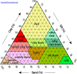
Interesting for You: Field Identification of Soil | Gravel V/S Sand, Silt & Clay
The wall is thicker at the bottom than at the top; the thickness at the base should be between one-half and three-quarters of the height. Gravity walls are very tedious to construct because they require large amounts of material. They are usually constructed with concrete and masonry. The size of the section of a gravity retaining wall can be reduced if a small amount of reinforcement is provided near the back face.
2. Semi-gravity retaining walls
In semi-gravity retaining walls the size of the section of a gravity retaining wall would be reduced and a small amount of reinforcement is provided near the back face.
3. Cantilever walls
A cantilever retaining wall has a relatively thin stem, is generally made of concrete, and steel is properly designed in the tensile zone to resist the tensile force and make it stable. The width of the footing is very important as it is designed to resist the sliding forces that the earth exerts upon the wall.
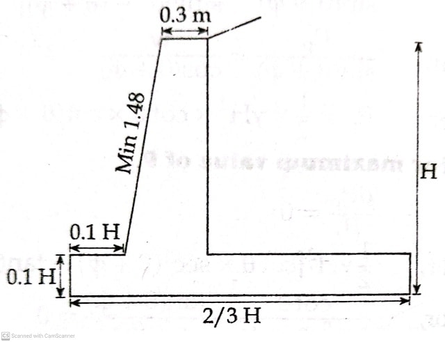
The wall requires significant steel reinforcing in both the footer and the wall structures. The steel should extend from within the footer up into the wall so that the two pieces become one integral unit. This type of wall is generally economical up to a height of 6-8 m.
4. Counterford retaining wall
A counter-fort retaining wall is similar to a cantilever retaining wall, but further supported by additional thin triangular-shaped walls, or counterforts, built at right angles to the main trend of the wall. The counterforts are provided at regular and required intervals along the wall and connect the back of the wall to the top of the raft. The footing, retaining wall, and support walls must be tied to each other with reinforcing steel.
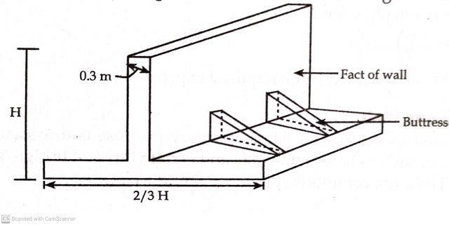
The counterforts are designed to reduce the shear force and bending moments in the stem and the base slab and add strength to the retaining wall. They are hidden within the earthen or gravel backfill of the wall. Counterfort retaining walls are economical at heights of more than 6-8 m.
5. Crib walls etc.
A crib wall is a box-type structure built from interlocking struts of timber, precast reinforced concrete, steel, or other material, and is usually infilled with soil or stone. The whole unit acts as a gravity wall.

- Crib walls are constructed without fixed joints,
- It has a segmented nature of the elements,
- crib walls are flexible due to this reason they resist differential settlement and deformation.
Stability Analysis of Earth-Retaining Structures
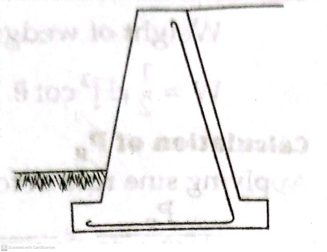
The figure below shows a retaining wall with a smooth back face and no surcharge. The active pressure P, acts horizontally as shown. The front face of the wall is subjected to a passive pressure (P) below the soil surface. However, it is uncertain whether the full passive resistance would develop Moreover, also the value of Pp is small so it may be neglected.

This gives more conservation design. The weight, W of the wall, and the active pressure, Pa, have their resultant, R which strikes the base at point D.
There is an equal and opposite reaction R’ at the base between the wall and the foundation. For convenience, R’ is resolved into the vertical and horizontal components (R’v, and R’H).
From the equilibrium of the system;
R’v=W and Rh’=Pa
The third equation for equilibrium, namely the movement equation, is used to determine the eccentricity e of the forces R’v relative to the center C of the base of the wall.
Obviously taking a moment about the toe;
R’v x = W x a – Pa x H/3
= {W x a – Pa x H/3}/ R’v
where, is the distance of the point D from the toe.
Thus, Eccentricity e= (b/2)
where, b is the width of the base.
For safe design, the following requirements must be satisfied.
- No sliding
No sliding When the horizontal resisting forces are greater than horizontal sliding forces then the wall does not fail under sliding.
This means,
µ R’v > RH
where, Rv, and RH are vertical and horizontal components of R respectively.
The factor of safety against sliding is,
Fs= Resisting horizontal force / Sliding force
Fs= µR’v / RH >1.5
where µ= coefficient of friction between the base of the wall and the soil (= tan δ).
2) No overturning
If the resultant is maintained within the body of the dam, there will be no overturning. The wall must be safe against overturning about the toe. The factor of safety against overturning is given by,
F0=∑Mr / ∑Mo≥ 2
where, Mr= Sum of the retaining moment about the toe.
Mo = Sum of the overturning moment about the toe.
3) No bearing capacity failure
Middle third rule:
The pressure caused by Rv at the toe of the wall must not exceed the allowable bearing capacity of the soil.
The pressure distribution at the base is trapezoidal with a maximum at the toe and a minimum at the heel. The intensity of pressure can be calculated by using the relation.
Qmax, min= Rv/b{1±6e/B}
qmax= Rv/b{1+6e/B}
qmin = Rv/b{1-6e/B}
If the resultant of Bending stress and Normal stress is equal, then the tensile stress (-ve value) will equal to zero,
Hence, e= ±B/6
Therefore, For no tension to develop at the base, the value of the eccentricity e should not exceed b/6.
There is permissible eccentricity on either side of the center point. So, if the resultant force passes through the middle section having the length (B/3), then tensile stress will not be developed at any points of the considered section of the retaining wall or Dam. This is called the ‘Middle third rule’.
When e=0 then qmin =0.
When e >b/6, qmin<0 tension will be developed and the heel of the wall will be lifted up. This situation should not be allowed to develop.
The factor of safety against bearing failure is given by,
Fb = qna/ qmax ≥3
Where, qna = Allowable bearing pressure.
You’ll also Like:
- Underpinning Methods, Procedure, Use in Foundation Strengthening and Repair
- Unified Soil Classification System (USCS)
- Types of Scaffolding Used in Construction and Parts
- Functional requirements of building| Components of Building structure & Parts
- Types of Stone Masonry: Ashlar Masonry, Rubble Masonry
- Hill Roads: design, construction, importance, Alignment, protection
- 19 Types of cement – Properties and Uses in…
- Concrete Admixtures – Types and Functions.
- Types of Formwork (Shuttering) for Concrete Construction and Application.


I think this is a very informative platform to civil engineers and I am damn sure to suggest my friend circle.
This is a great breakdown of the various retaining wall designs! I especially appreciate the explanation of how each type of wall achieves stability, from the inherent weight of gravity walls to the use of buttresses in counterfort walls.
The article mentions that the design of cantilever walls needs to consider the bending moment and shear forces acting on the wall. Could you elaborate on how these forces are calculated and how they influence the design of the wall thickness and steel reinforcement?
I’m interested in learning more about the engineering behind these structures.