
Flash Point and Fire Point Test of Bitumen
What is Flash point and Fire point of Bitumen?
The flash point of a material is the lowest temperature at which the application of test flame causes the vapours from the material momentarily catch fire in the form of a flash under specified conditions of test.
In practical view the fire point is the lowest temperature at which the application of test flame causes the material to ignite and burn at least for 5 seconds under specified conditions of test.

At high temperatures, bituminous materials emit hydrocarbon vapours which are susceptible to catch fire. Therefore the heating temperature of bituminous material should be restricted to avoid hazardous conditions. Flash point and fire point tests are used to determine the temperature to which bituminous material can safely be heated.
Objectives:
To determine flash point and fire point of the bituminous material.
Apparatus for flash and fire point test
The apparatus consists of:
- Pensky Martens closed Tester consisting of the following major parts:
- Cup . It is made of brass, the inside of the cup may be turned to a slightly larger diameter above the filling mark and the outside maybe tapered above the flange. The flange is about 12 mm in width and approximately 3 mm in thickness. It is equipped with devices for locating the position of the lid on the cup and the cup itself in the stove. A handle is attached to the flange of the cup.
- Lid. It includes a stirring device, cover proper, shutter and flame exposure device.
The stirring device consists of a vertical steel shaft of 2.5 mm to 3 mm diameter and mounted in the centre of the cup. It carries two bladed brass propellers. Cover proper is made of brass and fits the outside of the cup closely. It has four openings (see in the Fig. )
Opening A has an area defined by area of two concentric circles. Opening B and C are of equal areas and approximately half the angular width of opening A. Opening D is provided to grip the thermometer collar.
Shutter. 2.5 mm thick and made of brass . It is so shapped and mouned that it rotates on the axis of the horizontal centre of the lid. On one extreme position, the opening A, B and C of the lid are completely closed and when in the other extreme position, these orifices are completely opened.
Flame. Exposure device – having a tip with an opening 0.7 to 0.8 mm in diameter. The device is equipped with an operating mechanism which, when the shutter is in open position, depresses the tip so that the centre of orifice is between the planes of the under and upper surfaces of the lid proper. A pilot flame for automatic relightining of the exposure flame should be provided.
- Stove. It consists of an air bath and a top plate on which the flange of the cup rests. Air bath has a cyclindrical interior, 41.3 to 42.2 mm in depth. The air bath may be either a flame-heated metal casting or an electric-resistance element.
The top plate is made of metal and it can be attached to the air bath with the help of three screws in such a manner to leave an air gap.
- Thermometers. For low range values, it has measurement range from -7o to 110 oC and readable upto 0.5 oC. For expected higher values of flash and fire point, thermometer having a range of 90o to 370o and readable to 2 oC should be used.
Also read: Penetration test of bitumen and uses for Road construction.
Procedure
- For Bitumen Other than Cut Back Bitumen
- Clean and dry all parts of the cup and its accessories throughly .
- Fill the cup with the material to be tested upto the level indicated by the filling mark.
- Place the lid on the cup and set the latter in the stove.
- Insert the thermometer.
- Light and adjust the test flame so that it is of the size of bead of 4 mm in diameter. Apply heat such that the temperature rises at a rate of 5o C to 6o C per minute.
- Turn the stirrer at a rate of approximately 60 revolutions per minute.
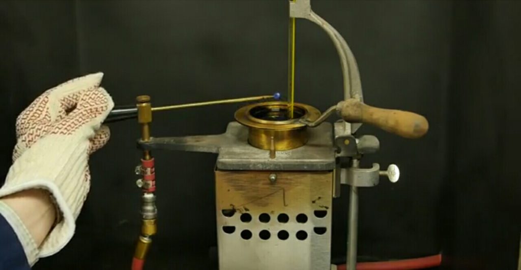
Apply the test-flame by operating the device controlling the shutter and test flame burner so that the flame is lowered in 0.5 second, left in its lowered position for one second, and quickly raised to its high position. Discontinue stirring during the application of test flame.

- Apply the test flame initially at a temperature 17oC below the expected flash point . Thereafter apply the test flame at an interval of 1o C for the range above 104 oC. For the temperature range above 104o C increase this interval to 2 oC.
- Note down the flash point as the temperature at which the flame application causes a distinct flash in the interior of the cup.
The duplicate test results should not differ by more than the following :
| Flash point range | Repeatability | Reproducibility |
| 104 oC and below | 2 oC | 3.5 oC |
| Above 104 oC | 5.5 oC | 8.5 oC |
For Cut-back bitumen
Procedure
- Fill the cup with the material to be tested.
- Completely fill the air space between the cup and the interior of the air bath with water having the same temperature as of the material.
- Proceed in same manner as in 4.1 except that rate of heating is between 1 oC to 1.5 oC per minute, the rate of stirring is 70-80 revolution per minute, and the test flame to be applied at each 0.5 oC rise in the temperature.
- Note down the test results; the duplicate tests should be within the limits specified in under 4.1 (viii)
Determination of Open Flash Point and Fire point
The standard Pensky-Martens tester and thermometers as prescribed in previous method is used with slight modifications. The cover of the cup is replaced by a clip which encircles the upper rim of the cup and carries the thermometer and test flame. The test flame is fixed at the vertical axis of the cup and in level with the upper edge of the cup.
Procedure
- Follow the steps (i) to (v) in 4.1.
- Note the temperature at which a flash first appears at any point on the surface of the material.
- Continue heating until the oil ignites and burns for 5 minutes. Record this temperature as fire point.
- The duplicate test results should fall within the following range.
| Repeatability | Reproducibility | |
| Flash point | 8 oC | 11 oC |
| Fire point | 8 oC | 14 oC |
Precautions
- The test flame should neither be larger than stipulated nor be applied more frequently than specified as the surface layer may get super heated.
- The bluish halo that sometimes surrounds the test flame should not be confused with the true flash.
Record of Observations
Type of Material:
Type of Test: Closed/Open
| Property | Test | Mean | ||
| 1 | 2 | 3 | ||
| Flash point | ||||
| Fire point |
Interpretation of results
The determination of flash point is helpful in assessing the safe limits of heating the bitumen. The heating temperature of bitumen should be limited well below the flash point.
You’ll also like:
.Marshall mix design method, apparatus and procedure.
.Aggregate Impact value Test Apparatus, Procedure and uses.
. Aggregate Crushing Value Test – Determine Aggregate Crushing Strength.
.Penetration test of Bitumen.
.Ductility Test of Bitumen and uses for Road construction.
.composition test and uses for pavement construction.
.How concrete is made.

1 thought on “Flash Point and Fire Point Test of Bitumen”