
Cement Concrete piles |Cast-in-situ Concrete piles |Precast Concrete Pile
What is a concrete pile?
Concrete piles are made with reinforced cement concrete is a structural element of a deep foundation, and is vertically driven or drilled deep into the ground at the construction site. Cement Concrete Piles are excellent material using for pile foundation nowadays because cement concrete possesses excellent compressive strength. With the advent of reinforced cement concrete, the R.C.C. (concrete) piles become the most useful types of foundation and replace piles of other products fastly.
The R.C.C. (concrete) piles are divided into two groups:
(1) Cast-in-situ concrete piles
(2) Pre-cast concrete piles.

Cast-in-situ Concrete piles
In this type of concrete piles, a casing is inserted into the ground to make the bore hole. After that the bore is filled with cement concrete with placing reinforcement, if any. The case can be held in place or removed. The former piles are known as the cased cast-in-situ concrete piles and the latter piles are known as the uncased cast-in-situ concrete piles. Some of the various patented processes for this category are briefly described below.
Cased cast-in-situ concrete piles:
It is possible to see that the casing is vertical, straight and undamaged. But as the casing is to be kept along with the pile, it will increase the cost of these piles. The casing protects the freshly placed concrete against ground pressures, intrusions and movements as the concrete sets. The shell lengths are easily adjusted on the job during the installation process to suit the changing subsoil conditions.
The examples of these piles are:
(i) Raymond piles
(ii ) Mac Arthur piles.
(iii) Monotube piles
(v) BSP base-driven piles
(vi) Swage piles
(vii) Button-bottom piles.
(iv) Cobi pneumatic mandrel piles
- Raymond piles:
A system developed by Reymond In 1897, A. D. for a practical and economical way of placing cast-in-situ concrete piles is known as the Raymond pile system.
Following two types of Raymond piles are in common use:
(a) Raymond standard concrete pile
(b) Raymond step-taper concrete pile.

- Raymond standard concrete pile:
In Raymond standard concrete pile system a thin corrugated steel shell closed at bottom is used. The coat is pushed into the ground with a falling steel mandrel or core in the shell. When the desired depth is achieved, the mandrel is collapsed and withdrawn. Then the inspection of shell is done internally by maintaining the light from a mirror or flashlight or droplight. If the shell is found to be damaged during driving, it replaced by another shell. The concrete is then poured in the shell to finish up the pile as shown in fig. 1.
The usual tip diameter is about 200 mm and spirally wound wires are provided at 80 mm pitch to serve as reinforcement.
- Raymond step-taper concrete pile:
It consists of shell sections of suitable length. The bottom of the first shell to be driven is closed by a flat steel plate. The shell diameter increases at 25 mm in steps for each section of the shell. The required length of the pile is obtained by joining the proper number of sections by screw connections as shown in fig. 2. The process of forming the pile is the same as that of a standard concrete pile.
The advantages of this type of piles are:
(1) It grants on-the-job flexibility of length.
(2) It permits internal inspection after being driven.
(3) The steel shell left in position protects the fresh concrete filling.
- Mac Arthur piles:
As shown in( fig 3 to fig. 5): In this type of pile, a heavy steel casing with a core is driven into the ground as shown in fig. 3. After achieving the desired depth the core is withdrawn and a corrugated steel shell is placed in the casing as shown in fig. 4. The final step is to gradually fill and compact the concrete and remove the casing. The completed pile with a concrete core and the outer corrugated steel shell is shown in fig. 5.

- Monotube piles:
A monotube pile consists of a tapered fluted steel shell without a mandrel. The stack coatings are moved into the necessary depth and inspected within the coat. The shell is filled with concrete and the excess shell is cut off, where necessary. The welding process is used to extend the shell to the appropriate length. The shells are rigid and watertight. These piles are adapted from end resistance to friction-transporting soil to a variety of terrain conditions.
- Cobi pneumatic mandrel piles:
This pile consists of a corrugated steel shell and a Cobi mandrel. The four curved segments of the steel plate are supported by internal members and they are placed around a central expansible core to form a Cobi mandrel.
When in a loose state, the diameter of the mandrel is about 20 mm smaller than that of the shell diameter. The mandrel is placed in the shell and then nitrogen or air is forced into the mandrel at a pressure of about 9 kg/cm² or 0.90 N/mm². The mandrel thus becomes tight with the shell. Both are then lowered to the required depth. The mandrel’s valve is then opened, allowing nitrogen or air to escape. The mandrel collapses and it can then be easily withdrawn. The concrete is then laid in the shell.

- BSP base-driven piles :
This pile consists of a helically welded shell of steel plate. A concrete plug is provided at the bottom of the shell and driving is done by allowing the pile hammer to fall on the concrete plug as shown in fig. 6. After driving the casing to the required depth it is filled with concrete.
- Swage piles
In this type of piles, a pre-cast concrete plug of slight conical shape provided at the bottom of a steel shell. The three stages of forming these piles are shown in fig. 7 to fig. 9.
In the first stage, the shell and core are fixed at the top and driven on the top of the concrete plug. In the second stage, the core reaches the top of the concrete plug and the shell is forced round the taper of the plug forming a watertight joint. In the final stage, the core is removed and the shell is filled with concrete. These piles are used for hard soils or at places where it is desired to have watertight shells before concrete is placed in the shell.

- Button-bottom piles
In this type of piles, a concrete button is used at the bottom to provide an enlarged hole in the soil when the pile is being driven. The three stages of formation of these piles are shown in fig. 10 to fig. 12.
In the first stage, the steel pipe is set on the concrete bottom. At the second stage, the pipe, and button are driven up to the required depth and a corrugated steel shell is inserted Inside the steel pipe. In the last stage, the pipe is removed and concrete is poured after any necessary reinforcing has been installed.
- Uncased cast-in-situ concrete piles:
This types of piles are comparatively economical because no casing will be left in the ground. But skillful manpower is required to achieve this desired result. The uncased concrete piles are likely to be damaged from the subsoil pressure and ground movements which might result from the pile driving and from obstructions in the ground. It is essential to have close installation inspection in this type of piles as they cannot be inspected after they are installed and as they cannot be readily re-driven if heave or swelling occurs.
Uncased cast-in-situ concrete piles offer the following advantages:
(i)It is not necessary to have special handling equipment.
(ii) The concrete is not liable to damage from driving.
(iii) The cutting of excess lengths or building up short lengths is not required.
(iv) They do not require the storage space.
The examples of these piles are as follows:
- Simplex piles
- Franki piles
- Vibro piles
- Pedestal piles
- Pressure piles
- Under-reamed piles.
- Simplex piles
In this type of pile, a steel tube fitted with the cast-iron shoe is driven into the ground up to the required depth as shown in fig. 13. The reinforcement, if necessary, is put up. The concrete is poured into the tube and the tube is slowly withdrawn, leaving the shoe into the ground as shown in fig. 14. The concrete is not tamped and the pile is completed as shown in fig. 15.


Such type of pile is known as the Simplex standard pile. If tamping of concrete is done at regular intervals as the tube is withdrawn, it is known as the Simplex tamped pile. In the case of Simplex alligator jaw pile, the cast-iron shoe is provided by the alligator jaw point. The jaw opens as concrete is poured, allowing the concrete to flow. The tube is slowly withdrawn. In this type of pile, the shoe does not remain in the ground. Fig. 16 and fig. 17. show respectively the jaw point in close and open positions.
- Franki piles:
In this type of pile, a plug of dry concrete is formed as shown in fig.18. The plug is rammed by a hammer and in doing so, the plug drags the tube into the ground. When the required depth is reached, the tube is kept in position by cables as shown in fig. 2-19. Some quantity of concrete is then laid and rammed with such a pressure that the concrete plug is separated out from the tube as shown in fig. 20.
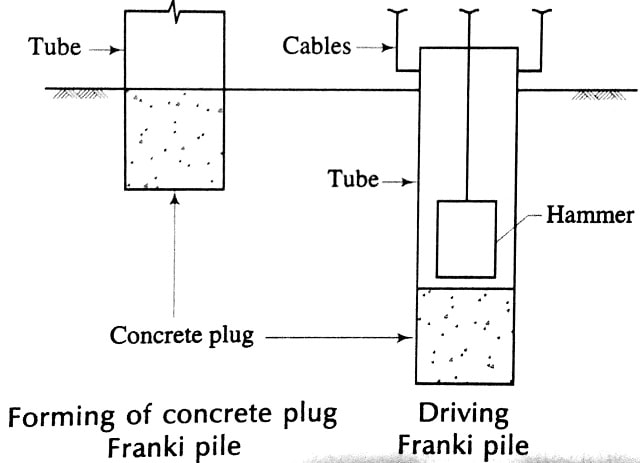
Successive layers of concrete are then laid and as concrete is being rammed, the tube is partly withdrawn. The completed pile is shown in fig. 21. The reinforcement, if necessary, is put up before withdrawal of the tube commences. This pile has corrugated surface and hence, it possesses considerable frictional resistance.
- Vibro piles:
In this type of piles, a steel tube with a cast-iron shoe is driven upto required depth as shown in fig. 2-22. The tube is connected to the hammer by extracting links. Art. 2-14-1] Foundations-It Spread and Pile Foundation
The tube is then filled with concrete and it is extracted by a succession of upward extracting and downward tamping blows as shown in fig. 2-23. This results in corrugations which provide a strong key for the pile with the surrounding ground. The reinforcement, if necessary, is put up before withdrawal of tube starts. The completed pile is shown in fig. 2-24.
In case of the Vibro enlarged base piles, a bigger shoe is provided which results in the increase of area of concrete block at the base.
For increasing the area of pile, the Vibro enlarged piles are employed. The tube is driven with the cast-iron shoe up to required depth. The concrete is deposited in the tube up to ground level and no reinforcement is put up in the concrete. The tube is withdrawn and then. It is re-driven with a new shoe on the newly placed concrete. The care should be taken to see that newly placed concrete does not start to set.
The pile is then finished by placing reinforcement, pouring concrete and withdrawing the tube. Thus, the cross-sectional area of the pile is nearly doubled and it increases the bearing power of the pile.
- Pedestal piles:
In the first stage of this pile, a casing tube with a core is driven upto the required depth. The bottom is made even as shown in fig. 2-25. In the second stage, the core is withdrawn and a layer of concrete is deposited in the casing as shown in fig. 2-26. In the third stage, the core is placed again in the tube. The pressure is applied on the concrete through the core and at the same time, the casing is withdrawn as shown in fig. 2-27.
In doing so, a concrete pedestal is formed as shown in fig. 2-28. The process is repeated till casing is completely removed.
- Pressure piles:
In the first stage of this pile, a hole is bored into the ground by means of an auger and as the boring proceeds, the hole is lined by a steel tube. By reaching the tube to the required depth, the boring tool is withdrawn properly. The first stage is shown in fig. 30. The reinforcement, if any, is then put up in the tube. In the second stage, a layer of concrete is laid and a pressure cap is provided at the top of the tube as shown in fig. 31.

The compressed air is then admitted through the air pipe and winch is applied to raise the tube. After that at the same time, the tube is lifted slightly and concrete is forced into the surrounding ground by compressed air. The process is repeated till the pile is completed as shown in fig. 32.
The care should be taken to see that some portion of concrete remains at the bottom of the tube when lifting of tube is stopped to receive a new layer of concrete. Otherwise, the water or loose soil may gain access to the inside of the tube, and also there will be loss of compressed air. This system uses compressed air for the consolidation and hence, it practically gets rid of the vibrations.
- Under-reamed piles:
These piles are successfully developed by C.B.R.I. Roorkee, U.P. (India) for serving as the foundations for black cotton soil, filled up ground and other types of soils having poor bearing capacity. An under reamed pile is a bored cast-in-situ concrete pile having one or more bulbs or under-reams in its lower portion. The bulbs or under-reams are formed by under-reaming tool. The diameter of an under-reamed pile varies from 200 mm to 500 mm and that of bulb varies from 2 to 3 times the diameter of pile.
The length of under-reamed piles is about 3 m to 8 m. A minimum bucket length of 300 mm is generally provided at the bottom. The piles are kept at the spacing of 2 m to 4 m. The safe load for an under-reamed pile varies from 200 to 400 kN. The under-reamed piles are also suitable for sandy soils with high water tables.
The load carrying capacity of the under-reamed piles can be increased by adopting piles of large diameter or by extending the length of piles or by making more bulbs at the base.
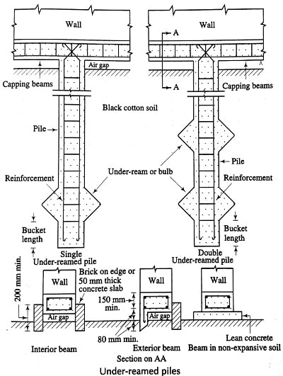
A single under-reamed pile consists of only one bulb at the bottom. When the number of bulbs at the base is two or more, it is known as a multi-under-reamed pile. Normally the vertical spacing between two bulbs varies from 1.25 to 1.50 times the diameter of the bulb.
The appropriate under-reamed pile is selected by the considerations of pile length, stem diameter, bulb diameter and number of bulbs. But the most important factor affecting choice of an under-reamed pile is the site conditions. In case of black cotton soils, the bulbs of under-reamed piles, not only increase the load bearing capacity, but also provide anchorage against uplift. For reclaimed soils, they provide large bearing area and for heavier loads, the multi under-reamed piles can be adopted.
The under-reamed piles are now being increasingly used under the following circumstances:
- taking the foundation through weaker strata into the firm ground when the depth of such strata is rather shallow;
- providing anchorage against the uplift forces; and
- providing foundation through filled-up soil deposits or reclaimed soils.
In India, the construction of under-reamed piles is mostly carried out manually. The equipment has been developed at the C.B.R.I., Roorkee (India). It is simple and light in weight. The basic tools are a spiral auger for boring, an under-reamer for making bulb and a boring guide to keep the hole vertical or at the desired inclination. The other accessories are also available to ensure work of better quality or to meet with the special requirements.
For deep and large diameter under-reamed piles, the use is made of tripod hoist with winch. For large construction projects, where speed is an important factor, a mechanised pile boring rig has also been developed. However the work is usually carried out by manual process with the use of tripod basis.
Fig. 1-33 shows the details of under-reamed pile foundations provided for a building. The piles are connected by a rigid capping beam which is suitably reinforced and over which the wall is constructed. An air gap of about 80 mm to 120 mm height is kept between the capping beams and the ground to ensure that the soil from below does not heave against the beams and the full load of the structure is taken by the piles.
Thus the air gap accommodates the soil movements without adversely affecting the superstructure. For interior beams, the brick on edge or 50 mm thick concrete slab is provided on both the sides to cover the air gap.
For exterior beams, the brick on edge or slab is provided to the inner face while the beam has a sharp edge penetrating the ground to the outer face. In case of non-expansive soils, however, the mass concrete of prop. 1:3:6 or 1:4:8 of 80 mm to 100 mm thick-ness is provided between the ground and the bottom of the beam.
The under-reamed piles have successfully proved to be a solution for constructing crack-free buildings.
In addition to safety, they grant the following advantages:
- They prove to be economical to the tune of about 15 to 20 percent over the conventional strip footings.
- The quantity of materials required for these piles is less.
- They do not require heavy excavation and hence the process can also be carried out in the rainy season.
- There is no backfilling when these piles are adopted.
- It has been found that an under-reamed pile becomes cost-effective when it is driven into hard strata at a short depth, allowing the entire working load to be carried in end bearing.
- Vibrations and noise generated during the construction of normal piles are eliminated.
Types of under-reamed piles:
The under-reamed piles adopted currently can broadly be divided in the following two categories:
- Bored and cast-in-situ concrete piles
- Bored compaction piles.
In case of former category, a bore of appropriate diameter is made generally using a spiral earth auger and the under reaming is done at the appropriate depth by a collapsible tool known as the under-reamer. The bore along with the under-reamed cavity is then filled with concrete after placement of reinforcement cage.
In case of bored compaction piles, the concrete immediately after placement is compacted by driving a suitable core. The reinforcement cage itself is sometimes driven through the concrete to effect the necessary compaction.
The number of bulbs in bored compaction piles is generally limited to 2 and the normal minimum spacing is kept 1.5 times the under-ream diameter. The bored compaction piles are claimed to have higher load carrying capacity to the extent of about 50% as compared to the normal under reamed piles of the same size.
The bored compaction piles suffer from the following drawbacks:
(a) There is danger of disturbing the concrete in lower depths after they have reached the initial set.
(b) There is possibility of side collapse of weak unlined soil and getting mixed with the concrete and thereby reducing the strength and integrity of concrete.
(c) This method may not work in subsoil water table without a liner being used.
Advantages of cast-in-situ concrete piles:
Following are the advantages of the cast-in-situ concrete piles:
- The light weight shells are used in the cast-in-situ concrete piles and these shells are easy to handle and to drive in the ground.
- No extra reinforcement is necessary to resist the stresses developing during the handling or driving operations only. This fact makes them economical.
(c) There is no wastage of material as the pile of required length is only constructed. Thus, it also eliminates the problems of lengthening or shortening of the pile.
(d) The piles are sound in construction as they are not driven into the ground by a hammer. The danger of breaking a pile is also thus eliminated.
(e) If the need arises, the additional piles may be constructed quickly.
(f) The extra cost of transport of pile is eliminated.
Disadvantages of cast-in-situ concrete piles:
Following are the disadvantages of the cast-in-situ concrete piles:
(a) It is difficult to maintain the reinforcement in correct position during construction of the pile.
(b) For an unreinforced pile, a slight movement of earth may break the pile.
(c) These piles cannot be constructed under water.
(d) It is not possible to have a proper control over the composition and design of these piles.
(e) The dry ground may absorb the moisture from the wet concrete. The piles are then weakened.
(f) The voids will remain in the piles if the concrete is not well-rammed and the reinforcement is displaced from its original position.
(g) The concrete is poured from the top and as it falls on the reinforcement cage before it reaches the bottom, the complete segregation of the concrete takes place and hence the concrete produced will be of poor quality.
PRE-CAST CONCRETE PILES
What is precast concrete pile?
These piles are manufactured in the factory and then driven into the ground. A bore is dug into the ground by inserting steel shell. If shell is left in place, it is called a shell pile. If shell is removed it is called a shell-less pile. The pre-cast concrete piles may be tapered or parallel-sided. They come in a variety of shapes, including square, octagonal, and circular.

The square and octagonal piles are cast in horizontal forms and the round piles are cast in vertical forms. The size of the pile may be 300 mm to 500 mm and length may be as much as 18 meter or more. However, from the considerations of the handling and lifting, the diameter generally does not exceed 600 mm.
The reinforcement is usually provided in all the pre-cast concrete piles to take up the stress during driving and handling operations. The main or vertical reinforcement consists of steel bars 20 mm to 40 mm in diameter and lateral reinforcement consists of the steel bars 5 mm to 10 mm in diameter. The spacing of lateral ties or binders is about 100 mm for a length of one meter at top and bottom of pile and for the intermediate length, it is about 300 mm. A concrete cover of at least 50 mm is to be provided for the reinforcement.
Fig. 2-34 and fig. 2-35 show respectively a square pre-cast concrete pile and an octagonal pre-cast concrete pile. At the toe of the pile, a steel shoe is generally provided and it is secured with the pile in such a way that it becomes a part of the pile. The steel shoe protects the toe and helps the pile in penetrating into the ground during driving.
Useful for You: Slump Test of Concrete, slump cone for Workability…
How are precast concrete piles installed?
The casting of the pre-cast concrete piles is carried out as follows:
(i) First of all, the shuttering for the pile is prepared and it is coated with the soap solution or oil to prevent adhesion.
(ii) The cage of reinforcement is prepared as per design and this cage is then placed in the formwork. The arrangement should be made to maintain a concrete cover of about 50 mm all-round the reinforcement cage.
(iii) The concrete is prepared in the required proportion. The usual proportions are 1:2:2 and 1:2:4. The ends are constructed in a rich mix. The size of the coarse aggregate varies from 10 mm to 25 mm.
(iv) The concrete is laid in the formwork and well consolidated. The concrete should be laid continuously till the pile is completely filled up. The vibrators are generally used for consolidation of concrete. It should be seen that the concrete is tapped in such a way that all the edges and corners of the concrete remain unbroken, sharp and straight when the formwork is removed.
(v) The forms are removed after three days and the piles are kept in the same position for about 7 days or so. Then the curing of piles is done in a curing tank and after a period of about three or four weeks, they become ready for use.
Advantages of pre-cast concrete piles:
Following are the advantages of the pre-cast concrete piles:
(a) The position of reinforcement in pile is not disturbed from its original position.
(b) These piles can be driven under water. For ground water containing sulphates more than 5000 parts per million parts of water, the concrete in the cast-in-situ pile may not set and under such circumstances, the pre-cast concrete piles will be the feasible alternative.
(c) It is possible to have a proper control over the composition and design of these piles as they are manufactured in a workshop. It is possible to see that the pile concrete and pile shaft are of good quality and integrity.
(d) Any defect of casting such as hollows, etc. can be found out and repaired before driving the pile.
(e) Any number of piles can be manufactured at a convenient place and may prove to be economical.
(f) These piles, when driven, are ready to take up the load. There is no wastage of time.
(g) These piles possess high resistance to biological Chemical actions of the ground. ,and
(h) The driving of these piles is smooth in the sense that it doesnot develop any adverse effect on the adjacent already drivenpile.
Disadvantages of pre-cast concrete piles:
Following are the disadvantages of the pre-cast concrete piles:
(a) These piles are heavy in weight and it is therefore difficult to transport, to handle and to drive them.
(b) The extra reinforcement is provided to resist the stresses developed during handling or driving operation. This fact makes the piles costly.
(c) The length of these piles is decided from trial bores. If additional length is required, it is to be made. A weak joint will be formed in this case. If the pile is too long, it is to be cut off which results in the wastage of material.
(d) If sufficient care is not taken, the piles may break during transport or driving.
(e) If piles are not available at a short notice, the delay of work would occur especially for emergency projects.
(f) The size and length of pile will depend on the available transport facilities.
(g) These piles require heavy pile driving equipments.
(h) The excessive driving can cause fine cracks in concrete. If the piles are driven from very soft to compact end bearing strata, the stresses produced 2 at the pile tip could be as high as 80% of the stresses produced at the pile head. If excessive driving can cause chipping of the concrete at the pile head, the developments of many cracks at the pile tip cannot be ruled out.
Underwater repairs of pre-cast concrete piles:
If pre-cast concrete piles which are used for the marine structures are damaged, they can be repaired with success by any one of the following methods:
- By lowering a permanent jacket either of steel or pre-cast concrete around the pile and filling it with tremie grout.
- Dobe By using an underwater-setting cement.
- By using an underwater-setting epoxy.
- using a reinforced concrete jacket cast in a temporary form.
- By using shotcrete which is applied over wire mesh.
For methods (b) and (c), the cement or epoxy is mixed in a small batch, lowered under water in a sealed container and placed by a diver, usually by hand. It is important to note that the piles to be repaired are thoroughly cleaned of mud, etc., by using wire brush or underwater sandblasting.
The piles which are repaired should be protected from erosion, wash, etc., until they have set. The period of completing the repairs will depend upon the type of material used and its time of set and it may vary from just few minutes to more elaborate methods such as clamps and forms.
The main disadvantage of the pre-cast concrete pile is its heavy weight. Hence the pre-stressed precast concrete piles have been developed. With the introduction of the pre-stressed technique, it has become possible to reduce the size of the pile and thereby making such piles of light weight. The pre-stressed concrete piles may be solid hollow with 200 mm to 300 mm diameter voids in the stem.
Following are the advantages of the prestressed pre-cast concrete piles:
(i) There is reduction in pick-up points. For instance, the square prestressed concrete piles of length 50 times the thickness can be handled with a single pick-up point and upto 60 times the thickness with two pick-up points.
(ii) They are light in weight and hence can be handled or transported easily and conveniently. It also results in less handling costs.
(iii) They are more durable in sea water because of the absence of cracks.
(iv) They can withstand extremely hard driving.
(v) They possess a larger moment of inertia than the conventional pre-cast concrete piles of the same dimensions because the concrete is all in compression.
(vi) They possess more strength as compared to the normal pre-cast concrete piles.
You’ll also Like:
- Slump Test of Concrete, slump cone for Workability…
- Types of Stone Masonry: Ashlar Masonry, Rubble Masonry
- Hill Roads: design, construction, importance, Alignment, protection
- 19 Types of cement – Properties and Uses in…
- Concrete Admixtures – Types and Functions.
- Types of Formwork (Shuttering) for Concrete Construction and Application.
- How Concrete is Made.
- Manufacturing of Portland Cement – Process and Materials.
- 7 Tips to Build a Prime Commercial Building


Guangzhou Deya Machinery Manufacturing Co. Ltd, national high-tech enterprise, is a science and technology service enterprises focusing on PHC pipe pile products industry with the core of technological innovation + service + big data application. Deya company provides the overall solution of intelligent production of cement products to customers, including the research and development of professional intelligent equipment, the cultivation of professional talents and provision of site management solutions, and so on.