Well Foundation: Meaning, Advantages, types, components & diagram
The well foundation is the most commonly adopted foundation for the major bridges. A well foundation is preferred to Pile foundation where the foundation has to resist large lateral forces, the river bed is prone to heavy score, heavy floating debris is expected during floods & where large boulders are embedded in the substrate.
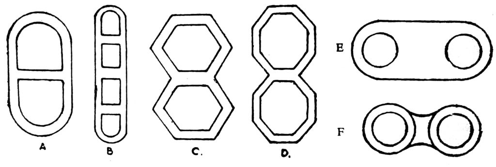
Shapes of well foundation
Following are the common shapes of the well which can be adopted:
1. Single circular
2. Twin circular
4. Double D
1. Dumb well
6. Twin octagonal
5. Twin hexagonal
7, Rectangular etc.
CHOICE OF PARTICULAR SHAPE
.The shape of well foundation is determined on the basis of the following:
1. Dimensions of the base of piers and abutments
2. The cost and ease of sinking
3. Tilt and shift considerations during the sinking
4. Horizontal and vertical forces acting on the well.

1. Circular well.
A circular well has the following advantages:
(a) For a given area of dredging the perimeter of the circular well is minimum.
(b) The ratio of sinking effort to skin friction is maximum.
(c) Sinking is more uniform than for any other shape,
(d) For short span bridges say up to 20 m, it is the best shape.
Interesting for You: Types of Foundation, footings for Building Construction and Uses
Disadvantages
A circular well has more diameter than required to accommodate the bridge pier in the direction parallel to the span of the bridge. Thus a circular well causes more obstruction to the waterway than the bridge pier.
2. Double ‘D’ shape.
(a) The disadvantages met in circular shape can be rectified by adopting double D shape Fig. 3
(b) It conforms to the shape of the bridge pier in plan.
(c) Dredge is also smaller for double D shape.
(d) For large piers double D shape wells are more economical than single circular wells.
3. Twin circular walls.
This class of wells have all the advantages of single circular and double D shape wells. Hence they are move preferable fig.3
Disadvantage
In this case the two wells are sunk close to each other. Thus they have the tendency to close in or move apart.
In abutments and wing walls where the tilt and shift is position is not important, a large number of small diameter wells have been adopted with advantage.
4. Double Hexagonal and Double Octagonal
Advantage.
They provide efficient grabbing to all parts of the curb. Fig. 3 (e) and (d).
Disadvantages
(a) Due to their sharp corners they produce more scour
(b) They are more likely to tilt as their sharp corner can dig more.
Fig. 3 (b) shows a rectangular shape with D-shaped ends.
Important of well foundation:
In situations where due to scouring or bearing capacity considerations, foundations are to be taken to greater depths than 5 to 7 m (15ft to 23ft), open excavation becomes costly and uneconomical due to the following reasons:
1. To retain the sides, heavy timbering is required.
2. Due to greater earthwork involved due to side slopes, progress in open excavation will be very slow.
3. There is a maximum possibility of scouring in the excavated material refilled in the open excavated foundation due to loose soil.
To overcome the above defects well foundation is needed.
You may Love: Underpinning Methods, Procedure, Use in Foundation Strengthening and Repair
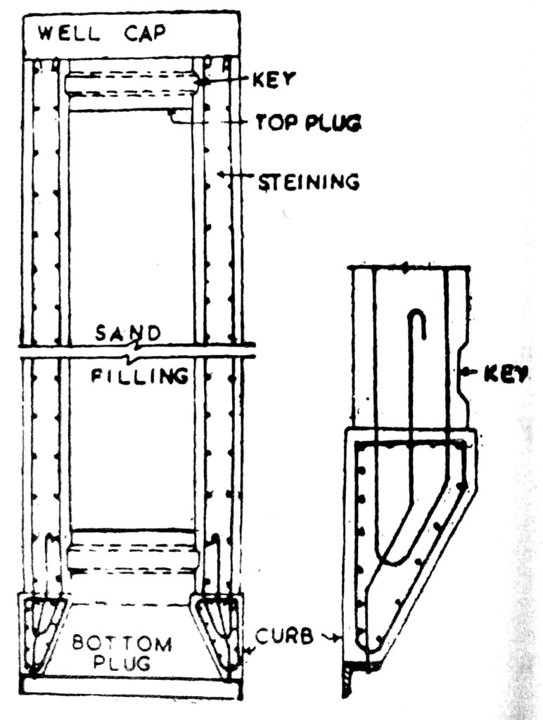
COMPONENTS OF A WELL FOUNDATION AND THEIR DESIGN

Following are the components of a good foundation
- Well curb and cutting edge,
- Staining
- Bottom plug
- Well cap
- Top plug
- Sand filling
All these are shown in Fig. 3.
a) Well curb.
It is circular in plan having wedge-shaped support at the bottom shown in Fig. 5. It can be made of timber or RCC. It is designed to support the weight of the well with partial support at the bottom of the cutting edge. For design purposes, a three-point support of the cutting edge resting on a log may be assumed. Actually speaking it is difficult an is the load on the cutting edge as it is quite uncertain as a considerable part of the load is borne by skin friction of the well.

Secondly, the effective depth e curt is also uncertain as the entire well acts as a deep girder residing bending and torsion. As the leading is occasional, working stress up to 90% of the yield stress may be allowed. A well curb also has to withstand the stresses de s and blows and also due to light blasting, sometimes resorted during sinking process when boulders are encountered. Fig. 4 shows the details of a well cut adopted for masonry staining.
b) Cutting edge.
The cutting edge should have as sharp an edge as practicable to cut the soil but it should be sufficiently strong to withstand the various stresses induced by boulders, blows, blasting, etc.
Generally in practice angle of 30 with the vertical or a slope of 1 horizontal to I vertical has been found quite satisfactory. In the case of concrete caissons, the lower portion of the cutting edge is wrapped with 12 mm steel plates which are anchored to the concrete by means of steel strips. To facilitate the sinking of a caisson and prevent air leakage from pneumatic caissons generally a sharp vertical edge is provided along the outside face of the caisson.
c) Staining thickness.
The staining may be of brick, stone, or RCC. Its thickness should be designed in such a way but at all stages, the well could be sunk under its own weight.
Theoretically, the steining thickness may be obtained by the following equation:
t= W (0.01H+ 0.1 D)
Where,
t = Minimum thickness of concrete
H=Depth of well below bed level.
D=External diameter of well.
K= A constant whose valor varies with the type of soil. It is shown in Table 1.
Table 1
| Types of soil | Value of K |
| Sandy soil | 1.1 |
| Soft Clay | 1.1 |
| Hard Clay | 1.25 |
| Hard soil with boulders | 1.3 |
The thickness of concrete staining in no case should be less than 4.5 cm. The corresponding thickness of brick staining should be about 10 cm more than the concrete staining. Fig. 1 shows concrete staining and well curb details of reinforcements.
Generally, the thickness adopted is given below:
Table 2. The outside diameter and steining thickness
| Outside diameter ‘D’ in meter | Steining thickness in meter |
| 3.0 | 0.75 |
| 5.0 | 1.20 |
| 7.0 | 2.00 |
The unit skin friction increases with depth. At a given depth, the skin friction is equal to the coefficient of friction µ x lateral earth pressure. Actually, it is very difficult to assess it very accurately. For design purposes following values may be adopted as suggested by TERZGHI and PECK are shown in Table 3.
Table 3. Soil with skin friction.
| S. No. | Types of soil | Skin friction in t /m2 |
| 1. | Dense gravel | 4.9 to 9.4 |
| 2. | Dense sand | 3:42 to 6.84 |
| 3. | Loose sand | 1.22 to 3.42 |
| 4. | Very stiff clay | 4.9 to 19.5 |
| 5. | Silt and soft clay | 0.73 to 2.93 |
It has been experienced that greaser skin friction requires greater sinking efforts and thus it ends de sinking of the well. This method should be adopted to reduce the skin friction while sinking the well frictional resistance depends upon the roughness of the surface of contact, following devices may be adopted to reduce the roughness of the surface:
1. The outer surface of the well staining can be given a smooth plaster coating which is is true without warps and kinks.
2. Friction can also be reduced by flaring the well.
3. By applying certain paints which can give a smooth and clear surface to the staining and should enough not to be rubbed during sinking operation.
4. Injecting bentonite solution on the outer surface of the well has been reported to reduce the skin-friction considerably.
New for You: Cement Concrete piles |Cast-in-situ Concrete piles |Precast-Concrete Piles
(d) Bottom plug.
The bottom plug generally is made of cement concrete. It is designed to withstand the upward thrust of the soil pressure including pore pressure minus self-weight of bottom plug and sand filling. It is given a shape like a bowl as to have an inverted arch action No reinforcement is provided is Following formulae may be used to calculate the thickness of the plug.
t²= 1.18 R² q / fc – for circular wells
t²= 3qb² / {4 fc 4fc (1 + 1.61 σ)} – for rectangular wells
where ,
t=thickness of bottom plug.
q=unit bearing pressure against the base of well.
f = flexural strength of the concrete sealer.
b= short side of well.
σ = ratio of the short side and long side of well
R = radius of well base
(e) Well cap.
It is designed as a beam to support the weight of per etc.
DEPTH OF WELL FOUNDATION
The depth of a well foundation is selected on the following criteria:
- The well should be taken deep enough to rest on a firm stratra having adequate bearing capacity to withstand the loads transmitted by the super structure through piers or abutments
- The grip or embodded length below the lowest scour level should be adequate. This is required in Atition to a depth as given by Rankin’s termuls, to develop sufficient passive resistance to count the overturting moment due to horizontal forces acting on the bridge deck as well as due to wind and water forces.
(a) As per IRC code the grip length should be less than 1.33 R below H.FL.
(b) As per Indian railways practice grip length should not be less than 1.5 t below the H.FL.
(c) Further the depth of embedment below scour level for piers and abutment should not be less than 20 in tor arch bridges and 1.2 m for piers and abutments supporting other types of bridges
Where R is the depth of sour.
R = 2 RL
Where RL is the normal scour depth as given by Lacey’s equation
For North Indian rivers of scour can be calculated by the following formula:
RL = {q²/f}^ (1/3)
Q= discharge intensity,
f= Lacey’s silt factor.
Scour level = H.FL. – R
= HFL-2RL
FORCES ACTING ON A WELL FOUNDATION
Generally following forces act on a well foundation:
Vertical Forces
1. Self weight,
2. Buoyancy,
3. Dead load of super structure
4. Dead Ioad of bearings and piers
5. Live lead transferred through the piers
6. longitudina forces,
7. earth pressure,
8. temperature stresses,
9. sismic forces,
10. centrifugal forces,
11. wind loads,
12. Impact loads.
Horizontal Forces
1. Braking and a tractive effort of the moving vehicles.
2. Farce on account of the resistance of the bearings against movement
3. Forces due to flowing water.
4. Wind pressure.
5. Seismic force
6. Earth pressure
7. Centrifugal forces.
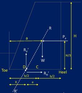
The magnitude, direction, and application of all the above forces can be determined under the worst possible combinations. These forces can be replaced by two horizontal forces P and Q. and vertical forces W as shown in fig.7.
P= resultant of all horizontal forces in the direction across the pier.
Q= resultant of all horizontal forces in the direction along the pier.
W= resultant of all vertical forces.
Sinking of well for well foundation
For the sinking process of well the following operations are carried out:
1. Laying of well curb
2. Contract of staining
3. Sinking operation
4. Tilts and shifts and their rectification
1. Laying of well curb
The well carb may be of steel or R.C.C., R.C.C. well curb has been shown in Fig 5. In the dry bed of the river, laying of well curb does not present any difficulty. In dry bed areas, a pit somewhat larger in diameter has the part is excavated up to about half a meter above the subsoil water level and the well curb is laid.
In case there is water in the river, table coffee dams are constructed around the le of the wall, and islands are formed. It the depth of water is shallow, an earthen cofferdam is made around the site, but in case of the water depths more, their sheet piling or caissons are used. After forming the islands the water is pumped out.
In case the R.C.C curb is desired to be laid, the center point of the well is marked accurately, and the cutting edge is placed on a level plane. In order to distribute the load evenly and avoid uneven setting of the cutting edge during concreting operations, wooden sleepers should be inserted at regular intervals below the cutting edge. These sleepers should be removed after the shuttering of the well curb is removed. Generally the outer shuttering is made of timber or steel while the inside shuttering of the well is made of brick masonry built to proper profile and plastered.
Now the curb reinforcement is placed in position properly and all the concreting casted is done in one continuous operation. Generally, vertical bars of staining are placed before concreting. These bars should project at least 2 m above the top of the curb.
2. When the concrete is set, the shuttering is removed at least after 24 hours. Now the brick or stone masonry staining is built over the curb.
The height of first stage staining should not be built more than 2 meters and subsequent height should at a time be built or raised more than 5 meters at a time. To build the staining in one straight line from top to bottom is absolutely essential. This aim can be achieved by building the staining with straight edges of angle iron. The lower portions of the straight edges must be kept butted with the masonry of the lower stage throughout building operations of the fresh masonry.
In building masonry for well steinings plumb bobs should not be used under any circumstances. Generally, it is desirable to keep the stages of masonry work at the location of joints in vertical staining bars. The masonry is cured well for 48 hours before the sinking operation is started. After sinking 1st stage completely, all the damaged portion of the stay all the damaged portion of the staining at the top should be removed and repaired properly before the start of the next stage masonry.
3. Sinking operations.
When the curb and 1st short stage of staining are completed, the well is ready to be sunk. A platform with the help of sleepers is formed and a tripod is erected over it with a central pulley, Weight is applied over this platform by putting empty gunny bags full of earth. This helps the well to sink quickly. The well is sunk by excavating the material from inside of the staining under the curb. In the initial stages of sinking the material is excavated by sending workers inside the well and excavated material is taken out through buckets pulled over the pulley hung over a tripod.
In the initial stages, the well is very unstable and the progress can be very rapid with little excavation. While carrying out this operation great care should be exercised to see that the well sinks vertically and should never be allowed to go out of the plumb.
Manual excavation inside and under the curb is possible until the depth of water in the well is up to 1 m. After this stage dredger or Jham can be used Dredger is a pipe about 2 m long with sharp cutting edges. A flap value is attached to its lower edge, which does not allow the excavated material from the dredger to fall.
In case a clayey stratum is to be pierced through, a rail chisel may be used. If the soil is not very hard, hot hard enough, not to be excavated by Jhams, phawara jhams can be used. As the well sinks deeper, the skin friction on the sides increases progressively. Thus to overcome this skin friction and buoyancy, additional weight: is applied on the platform. The loading by the platform is known as Kentledge.
During sinking operations pumping out of water from inside the well is effective under certain conditions. In the initial stages of sinking, pumping should not be allowed. In order to minimize the chances of tilt and shift dewatering should not be allowed till the well has passed deep enough or through a ring of clayey strata. When the well has been sunk to about 10 m depth, complete dewatering should not be allowed.
After this depth, sinking operations should be carried out by applying weight on the platform, chiseling, grabbing, etc. The hard soil may be removed by gelatin charges. When all these methods fail, then dewatering can be resorted to depress water level up to 5 m only.
In practice sometimes it has been observed that the sinking of well stucks up and the normal methods of dragging and kentledge fail to sink it further. In such situations the friction resistance developed on the out periphery of the well may be reduced to a great extent by forcing a jet of water around the outer face of the well. This method is effective only for well sinking in sand strata.
DIFFICULTIES DURING SINKING OF WELLS
During the sinking of the well following difficulties are found:
- Sand blowing.
- Tilting of well.
- Shifting of well.
- Sand blowing.
In sandy strata during the dewatering process sand particles also come with walm, casing cavity in the ground. This cavity causes wide cracks in the ground around the well under sinking operation. During the sinking operation, sand caves in the well and suddenly is filled in the well. This process is known as sand blowing. The sand blowing may cause fatal accidents resulting in burying the workers and machinery inside the well under the sand.
During sinking operations, if sand blowing is suspected, the dewatering operation should be stopped and men, machinery is taken out from the well. Now the bundles of grass and other such materials island bound the staining of well. This will check the possibility of sand blowing
Interesting for you: Cement Concrete piles |Cast-in-situ Concrete piles |Precast-Concrete Piles
Tilts and shifts.
In order to have a durable and strong structure, it is very essential that the wells are so straight and at the correct position. Suitable precautions should be taken to avoid tilts and shits. Following precautions are suggested to avoid tilts and shifts in the wells.
1. The outer surface of the well curb and staining should be as smooth and regular as possible
2. The cutting edge of the well curb should be of uniform thickness and sharpness as a sharper edge has a tendency to sink more than the blunt edge.
3. The radius of the well curb should be more at least by 2 to 4 cm than the outside radius of the staining of the well.
4. The dredging should be done uniformly on all sides of the well in the case of a single circular well and in both pockets in a twin well. The tilts and shifts of the well should be checked carefully and recorded. If the tilt exceeds more than I in 200, sinking should be supervised with special care, and measures to rectify it should be taken immediately. Any of the following measures can be employed as the case may be:
- Regulation of grabbing.
Unequal dredging causes tilt. If the well has not been sunk to a great deepen and tilt occurs. In that case, it can be rectified by excavating the earth under the higher side of the as shown in fig. a.
If the well has been sunk to sufficient depth, in that case a hole is made in the staining near the ground level on the higher side, as shown in Fig. (b). Then the rope of the dredging is pulled towards the higher side by hook as near to the curb as possible. To cut the soil on the higher side.
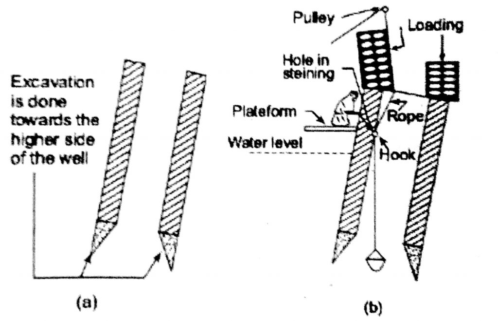
Application of eccentric loading.
In order to provide necessary sinking effort normally a kentledge is used on the well, te empty cement bags full of earth or concrete blocks are placed over the platform. In case of a tilt, in order to provide greater sinking effort on the higher side of the well, eccentric loading is applied as shown in Fig. (c). As the sinking progresses, heavier loads on higher sides with greater eccentricity are required to rectify with balance the tilts.
In large-size wells to be sunk to great depths eccentric loading varying from 400-600 tonnes with eccentric loading from 3 to 4 m have been used. In such cases to support such heavy loads welded frames are needed.

Water jetting or digging pit outside the higher side.
In this method to reduce the skin friction of the staining on the higher side a pet of water is forced. This method if used alone may not prove very effective but provides good results if used along with other methods.
- Excavation under the cutting edge.
If a stiff strata is met on the higher side, the tilled well cannot be straightened without excavating under the cutting edge. In such cases, it rotates and the safe wall should be dewatered and open excavation can be carried out under the cutting edge of the higher side. If dewatering is not possible or unsafe, divers should be sent inside the well to loosen the strata.
- Providing temporary obstacles below the cutting edge.
Sometimes in order to check the further tilt of the well, wooden sleeper pieces are put temporarily below the cutting edge of the curb while attempting other methods to rectify the tilt (Fig. G).
The above effect can also be obtained by putting a hook under the cutting edge and pulling it by the steel rope and winch as shown in Fig. (e).
Pulling the well.
This method is effective only in the early stage of sinking. The sleepers are places) vertically around the well and pulled towards the higher side by placing one or more steel ropes round the sleepers. This is done to distribute the pressure over larger areas of the well staining (Fig. f.
Related Post: Pile foundation
Strutting the well.
This method is used to check further increases in the tilt of the well rather than rectifying it.

PUSHING BY JACKS
The well may be brought to a vertical position by pushing it with the help of hydraulic or mechanical jacks applied on the tilted side of the well.
Shifting of well. During bringing the tilted well in true vertical position the center line of the well is displaced from its actual center line. This causes the shifting of well on either side. Shifting of well will cause eccentric load on the well and change in the bridge span length. Actually the main cause of shifting in the tilt of well.
You’ll also Like:
- Underpinning Methods, Procedure, Use in Foundation Strengthening and Repair
- Types of Scaffolding Used in Construction and Parts
- Functional requirements of building| Components of Building structure & Parts
- Types of Stone Masonry: Ashlar Masonry, Rubble Masonry
- Hill Roads: design, construction, importance, Alignment, protection
- 19 Types of cement – Properties and Uses in…
- Concrete Admixtures – Types and Functions.
- Types of Formwork (Shuttering) for Concrete Construction and Application.